Roadmap Drawings
From Career Pathways Tutorial
(→http://oregon.ctepathways.org/common/silk/cog.png Drawing Properties) |
(→Roadmap Drawing Properties) |
||
| Line 6: | Line 6: | ||
Both of the <b>Roadmap Drawings</b> and <b>POST Drawings</b> feature lists function the same way. Click the above title link to learn how to navigate it! | Both of the <b>Roadmap Drawings</b> and <b>POST Drawings</b> feature lists function the same way. Click the above title link to learn how to navigate it! | ||
| - | ==[[Roadmap Drawing Properties]]== | + | ==[[Roadmap Drawing Properties|Drawing Properties]]== |
Here you have access to detailed information and properties settings about each Roadmap drawing, as a whole - inclusive of all versions created for that drawing. | Here you have access to detailed information and properties settings about each Roadmap drawing, as a whole - inclusive of all versions created for that drawing. | ||
Revision as of 04:48, 5 November 2010
Due to browser compatibility issues, please use the latest version of Google Chrome or FireFox when using the Career Pathways Roadmap Web Tool.
Roadmap Drawing List
Both of the Roadmap Drawings and POST Drawings feature lists function the same way. Click the above title link to learn how to navigate it!
Drawing Properties
Here you have access to detailed information and properties settings about each Roadmap drawing, as a whole - inclusive of all versions created for that drawing.
Adding a New Drawing
Each drawing must have a unique Occupation/Program name. The Web Tool stores and references each drawing by organization abbreviation and drawing Occupation/Program name.
- Click
 at the top of the drawing list to create a new Roadmap drawing.
- The screen will refresh to look like this:
-
- Select an applicable Oregon Skill Set from the drop-down list.
-
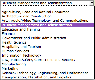
- NOTE: This will be displayed under the drawing title bar on your roadmap drawing.
-
- Select an Approved Program Name from the drop-down list. This will be your drawing title unless you provide an Alternate Title.
- If "Not Listed", select "Not Listed" from the drop-down list and provide an Alternate Title.
- NOTE: This has been done to help avoid typographical errors and maintain consistency in the roadmap titles. This list was taken directly from the Oregon Community College Viewbook of Approved Career and Technical Education Program, January 2009. As new programs are approved they will be added to this drop-down list.
- Alternate Title: If the program name you need is "Not Listed" (in the approved drop-down list), you can manually type your desired program name here. In addition, you can override the display of the Approved Program Name in the drawing title bar with a customized title here.
- Type a short and descriptive title for your drawing, such as "Accounting", "Game Programming", or "Culinary Arts - Food Service Management".
- NOTE: Please do not add your Organization's abbreviation to the title, or the words "Career Pathway", as these are automatically added by default.
- Your Organization name is confirmed below.
- Click

- Your new drawing and Version 1 has now been created. You are now viewing the drawing canvas to start creating your new drawing.
- Your Organization abbreviation, the Career Pathways logo, drawing title, and Oregon Skill Set are automatically placed in and under the drawing title bar at the top of the drawing canvas.
- To edit, go to
 Drawing Properties. Changes to the title and skill set will affect the entire drawing, not just a specific version.
- To edit, go to


Renaming Drawings

NOTE: Please do not add your Organization's abbreviation to the title, or the words "Career Pathway", as these are a part of the title bar by default. To rename a drawing:
- From the Roadmap drawing list or the drawing canvas TOOLS menu, click on Drawing Properties to the left of the drawing title.
- At the top of the Drawing Properties screen is a title bar confirming the Organization's abbreviation (such as "LCC" for "Lane Community College"), and the words "Career Pathways" followed by the assigned title for the drawing.
- Changes are saved automatically, and displayed in the drawing title bar at the top of the screen for confirmation.
- Approved Program Name: Select an Approved Program Name from the drop-down list. This will be your drawing title unless you provide an Alternate Title. Once selected, the Oregon Skill Set will be automatically assigned.
- If "Not Listed", select "Not Listed" from the drop-down list and provide an Alternate Title and manually select the Oregon Skill Set.
- NOTE: This has been done to help avoid typographical errors and maintain consistency in the roadmap titles. This list was taken directly from the Oregon Community College Viewbook of Approved Career and Technical Education Program, January 2009. As new programs are approved they will be added to this drop-down list.
- Alternate Title: If the program name you need is "Not Listed" (in the approved drop-down list), you can manually type your desired program name here. In addition, you can override the display of the Approved Program Name in the drawing title bar with a customized title here.
- Type a short and descriptive title for your drawing, such as "Accounting", "Gaame Programming", or "Culinary Arts - Food Service Management", and click
 .
.
- The title bar will automatically update to reflect your changes.
- Type a short and descriptive title for your drawing, such as "Accounting", "Gaame Programming", or "Culinary Arts - Food Service Management", and click
- Oregon Skill Set: if no Approved Program Name was selected, which automatically sets the skill set category, you can assign an applicable category from the provided drop-down menu of choices
-
- NOTE: This will be displayed under the drawing title bar on the drawing canvas. Adjustments to your layout/design may be required.
-
- Return to the drawing list by clicking back, the back arrow on your browser, or clicking Roadmap Drawings from the side navigation.
- Return to editing the drawing by clicking
 Draw/Edit Version from the Version Actions menu.

TOOLS Orientation

- View the HELP menu on the drawing canvas for a complete list of features.
- Right-click an object on the drawing canvas for a menu of customizing options.
- When selected, boxes, connections, lines and arrows show a blue frame, with a green control point at the start, and a red control point at the end. The object's menu can be brought up by right-clicking anywhere within this frame.
Drawing Canvas Print Frame
- Visible in "draft" mode only, these non-printable gray borders provide a visual guide for fitting your Roadmap design to a printer friendly portrait print layout. Please note: these are only guides! Always use the Print This Version tool feature to review your work for desired print layout.
Grid Settings
- Right-click the drawing canvas to change default grid settings.

- Changes to grid settings are not saved, and will return to default settings upon exiting the drawing.
Add Objects
- Right-click the drawing canvas for a menu to add new objects (box, line, arrow) in the same location that was right-clicked.

NOTE: Lines and arrows must be manually aligned with box objects, and are discouraged. These have been removed from the TOOLS menu to transition users into using the Connections feature. Please use Connections for ease of layout adjustments and ADA compliance. Connections can translate the relationship of box objects in text only views of these drawings.
Edit Box Titles
- Right-click box objects to Edit Title. This enables an in-place text editor for the box's title.
- The existing text is highlighted by default. Use your keyboard and/or mouse to highlight and edit text.
- Click outside of the box, or hit TAB on your keyboard, to accept changes.
- Titles default to all CAPS.
- Please do not exceed 2 lines of text for your box titles.
Edit Box Content
WARNING: DO NOT copy and paste text from MS Word. Hidden code can cause undesired formatting results, printing issues or glitches that can permanently damage drawings. Please only copy and paste from generic text editors.
- Right-click a box object and select Edit Content. The box's content editor will open in a pop-up window.
- A WYSIWYG editor will open for text entry and formatting.

Undo/Redo
- Click the undo/redo arrows to undo/redo text and formatting changes. Only able to undo changes made during the current editing session.
Line Spacing
- Hit the Enter/Return key on your keyboard to automatically double space your content. This is called paragraph spacing.
- To single space, hold down SHIFT + Enter/Return key for a new single spaced line of content.
Spell Check
- Click the ABC check icon to spell check box content.
- Errors will be underlined in red. Right-click marked words for suggested corrections.
- Select the corrected word, or select "Ignore Word" or "Ignore All".
Insert/Edit Hyperlink
- Highlight the text a hyperlink will be created with.
- The Insert/Edit Link icon will become active.
- Click the Insert/Edit Link icon to open the "Insert/edit link" pop-up box.
- Provide the link URL. The "target" link is set to open in a new window, by default.
- Optional: Provide a link title. This will not appear in the content.
- Click "Update" to save and return to the content editor.
Remove Hyperlink
- Highlight the desired hyperlink. The Unlink icon will become active.
- Click the Unlink icon to remove the hyperlink.
Insert Image
- Click the Insert Image icon to open the "Insert/Edit Image" pop-up box.
- Provide a URL for an image located online.
- Optional: Provide an image description, and customize the alignment, dimensions, border, vertical and horizontal space.
- Click "Insert" to save and return to the content editor.
Insert/Modify Tables
- Place your cursor in the desired location for the table you wish to add.
- Click the Insert Table icon to open the "Insert/Modify table" pop-up box.
- Change the values for "Cols" and "Rows" as desired.
- Optional: Customize cellpadding, cellspacing, alignment, border, width, height, class and table caption. Explore Advanced tab options.
- Click "Insert" to save and return to the content editor.
- Click on the table to add content the table cells. Use the additional tools that are now active across the toolbar to modify table row and cell properties, merge cells, and insert and remove rows and columns.
- Or, click the Insert Table icon again to modify the table layout, make the desired changes, and click "Update" to save.
Edit CSS
For the more advanced user.
- Click the AA icon to customize inline CSS styling. An "Edit CSS Style" pop-up box will appear.
- Explore options and click "Apply" to see the changes save to your content box.
Edit HTML (Source Code)
For the more advanced user.
- Click the HTML icon to open the "HTML Source Editor" pop-up box.
- Edit HTML code with HTML and CSS as desired, and click "Update" to save changes to the content editor.
Deleting Objects
- Delete objects with the DELETE key or the object's right-click menu.
NOTE: There are no “save” or “undo” features built in to the Web Tool. Drawing changes are saved instantly. Confirmation is provided before any objects are deleted from the drawing canvas.
Connections
A dynamic connection that moves between two or more box objects as layout changes occur. Please use Connections for ease of layout adjustments and ADA compliance. Connections can translate the relationship of box objects in text only views of these drawings.

- Right-click the starting box to select Start Connection Here;
- Right-click the ending box to select End Connection Here from the menu.
- A dynamic connection will appear between the two boxes.
Try this! Move the boxes around to see how the connection moves with the boxes. Slide the starting and ending points on the boxes to adjust the layout, and customize the connection with the following menu options!
Right-click each individual connection line to access this menu:
- Start Point menu
- Sets the side of the box the line is drawn from: Top, Bottom, Left or Right.
- End Point menu
- Sets the side of the box the line is drawn to: Top, Bottom, Left or Right.
- Orientation menu
- Sets the orientation (horizontal or vertical) of the connection from the start point. This option is not available if segment is set to 1 (Direct Line).
- Segments menu
-
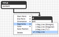
- Sets the number of segments in the connecting line:
- 1-Seg Line (Straight)
- 1-Seg Line (Diagonal)
- 2-Seg Line ("L")
- 3-Seg Line
- The default, 1-segment line, may not be visually connected to the end point. Adjust by moving the ending box, or selecting a different segment or orientation option.


- 1-Seg Line (Diagonal) creates a diagonal line to the destination box regardless of box position.

- Color menu
- Sets the color of the connection.
- Auto Position
- Detects box location to adjoining box, and resets connection to 1-Seg Line (Straight).
- Delete
- Permanently removes the connection, after confirmation.
- Can also perform same action by hitting the DELETE key on your keyboard.
Changing Object Color
- To change an object's colors, select the object and click a color from TOOLS color palette, or using Color on the object's right-click menu.
- Connections are automatically assigned the color of the box they start from. If you change the color of the box, the connection is automatically updated; however you can manually override the connection color as instructed above.
- Each Organization assigns its own selection of colors to the color palette, however default standards to all color palettes are: Dark Grey (#333333) and White (#ffffff).
Moving Objects
- Click anywhere on a box object, and drag and release your mouse at the desired location. When clicked, boxes are highlighted with a blue frame.
Resizing Boxes
- When selected, boxes are highlighted with a blue frame, with left and right blue control points. Click and drag either point to expand/retract box width.
- Box height is determined by content.
Positioning Objects
- When selected, boxes, connections, lines and arrows show a blue frame, with a green control point at the start, and a red control point at the end. The object's menu can be brought up by right-clicking anywhere within this frame.
- Click and drag the green start point or red end point to vertically or horizontally adjust the starting or ending location.
- Connection start and end points can "slide" to any desired location along the TOP, BOTTOM, LEFT and RIGHT edges of box objects.
- When dragging a box, line or arrow, hold down the ALT key (Option on Mac) to move the object without snapping to the grid.
- When dragging a start or end point for a line or arrow, hold down the Shift key to make the line snap to a vertical or horizontal layout.
Video Demonstration
View a short video demonstrating several key Web Tool drawing features here.
Deleting Drawings
There is no way to recover deleted drawings! Click the above title link to learn more.
Lock This Version
This feature is ideal when you are collaborating on a drawing, or want to compare versions without the risk of making accidental changes, and you are NOT ready to “publish”. Click the above title link to learn how!
Copy This Version
For copying existing drawings as new versions or as templates for new drawings. Click the above title link to learn more!
Print This Version
Click the above title link to about printing Roadmaps in the Web Tool.
Print To PDF
PDF documents are now automatically generated on the Web Tool server and always render the currently published version of your Roadmap Drawing, just like the HTML Links do. Click the above link to learn more!
Publish This Version
Published drawings are publicly accessible. If you are ready to embed or link to a drawing in a public website, click the above link to learn more!
Unpublish This Version
Ideal for test drawings, Roadmap Drawings that users don't want accidentally included in OLMIS Occupations Reports or other public websites, and for programs that are no longer being offered, but should not be deleted. Click the above title link to learn how!
Linking to OLMIS Occupational Reports
Introduction: Use this feature to add your published Roadmap drawings to selected OLMIS Occupational Reports. Making your published Roadmaps available in OLMIS will give job seekers around the state the opportunity to learn about your program. The added benefit to you is that prospective students browsing careers options on the OLMIS website will now be able to link to Roadmaps for the community colleges offering degree and certification programs in their field of interest. For more information, read the release notice regarding this feature.
NOTICE: Roadmaps that are linked to OLMIS with this feature will NOT be automatically added or changed on the OLMIS website. OLMIS synchronizes changes with the Web Tool on a nightly basis.
You can change, add or remove your links at any time by returning to the Drawing Properties page and repeating these steps.
- From the Roadmap drawing list or the drawing canvas TOOLS menu, click on Drawing Properties to the left of the drawing title.
- This OLMIS feature is only visible after a drawing version has been published, and only to users within their own Organization.
- Underneath the Approved Program Name, click
 Add Link. The screen will expand to display additional features:
-
- Click
 to search your published Roadmap drawing for links to OLMIS pages.
- The following text and search bar will appear, confirming that your search is in progress:
- If no links are found, text will appear confirming that "No OLMIS links were found in this drawing".
- If links are found, the screen will refresh to display names of OLMIS Occupational Reports, such as:
-
- Simply click the checkbox next to each occupation report page that you want your published Roadmap drawing to appear on. Select one or more occupational reports.
- To view the OLMIS Occupational Report for an occupation, click the hyperlinked occupation name. A new browser page will open.
- Once clicked, the selected occupation will be moved to the top of the list, automatically saving the selection.
-
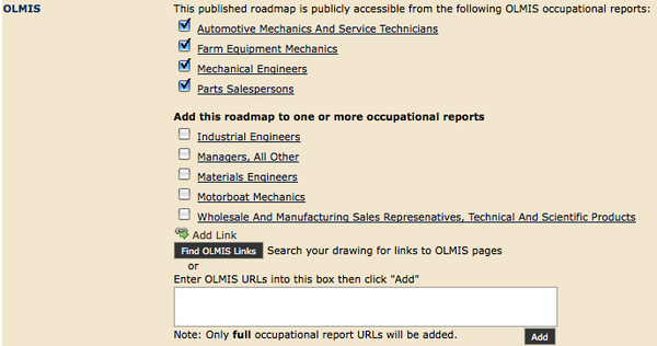
- Drawing Properties Page with Add Link feature active.
- To remove a link to a specific OLMIS Occupational Report, simply uncheck the box and it will disappear. If removed by accident, simply repeat steps 2-5 to relink your roadmap to that OLMIS Occupational Report.
- Alternately, you can manually copy and paste OMLIS URLs into the box provided. Click
 to save.
-
- Once added, the checkbox will be automatically checked, and the new occupational report added in alphabetic order to the confirmed list above.


Using the Correct OLMIS Links

In order for this OLMIS feature to recognize the Occupational Report links that you place in your Roadmaps you need to paste URLs for the FULL OCCUPATIONAL REPORT into the Insert/Edit Link feature for your Roadmap content, or for the ADD feature in the Drawing Properties page.
If you have are using the correct link it will have the text string "rpttype=full&action=report" in the middle of the URL, as in these examples:
For tutorials on how to embed Roadmap Drawings into public websites, click here: Embedding Roadmaps & POST Views
ADA/504 Accessibility Compliance
The Web Tool has undergone a series of changes that have been aimed in part at ensuring accessibility of Roadmaps and POST Drawings produced by it. Click the above link to learn how.